
Subzero Cooldown Dewar
Back to Subzero Cooldown
We no longer use this hardware. This page is here for historical reference only.
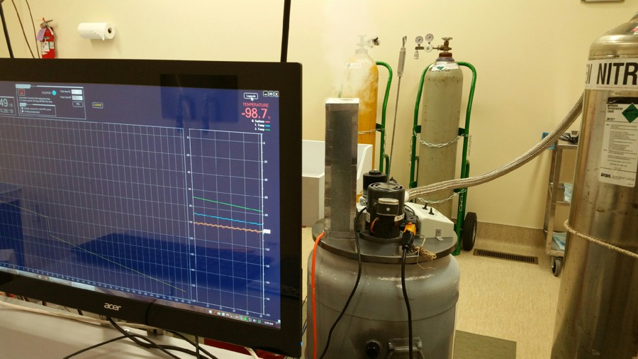
The cooldown dewar is controlled by the Subzero Cooldown Software for the final cooling down to liquid nitrogen temperature.
The Cryonics Institute cooling box is documented here.
Alcor's cooldown dewar is poorly documented here.
Suspended Animation's cooling box was documented here, but it now seems to be gone from their website.
This is our cooldown dewar:
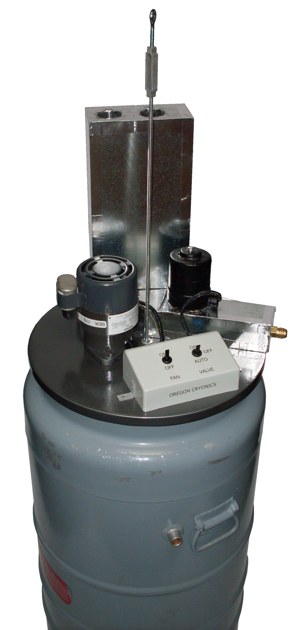
Components
The current cooldown dewar has had the control box shown in the photos removed. The text describes the current setup after the revision.
Dewar: LR-40, original lid removed
Lid: 2 circles of plywood sandwiching 3 circles of pink extruded polystyrene foamboard, 4 1/8" total foam thickness. All layers laminated together with epoxy. Entire assembly coated with epoxy and paint.
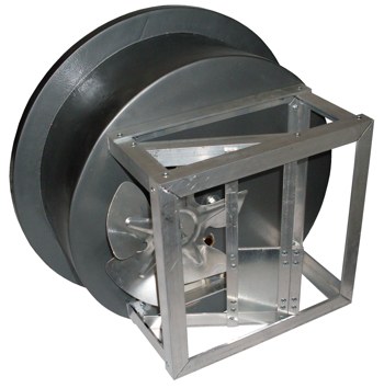
Fan: 1/8 HP motor, Dayton 3M292D, 3000 RPM, 1.8 A, 115 V, 5/16" shaft, clockwise rotation. Shaft adapter: 1/4" to 5/16". Ball bearings on a flange on underside of lid seals fan shaft hole to prevent passage of cold gas upwards. Bearing flange is loosely mounted because the shaft is not perfectly straight and it needs freedom to wobble slightly. 7" diameter fan blade, 1/4" shaft hole, RPM max: 3450.
Valve: Magnatrol 10M61. Pipe size 3/8", max 150 psi, AC model 120 v, 60 Hz, 25 Watts, normally closed. The pipe is heavily insulated with polyurethane foam. Frost forms and builds up on the exposed valve body, so there are plans to enclose it in polyurethane foam as well. Under the lid, the pipe opens directly above fan. The fan disperses the LN
Electrical connections: The short pigtails coming off the fan motor and valve are both enclosed in shrink tubing and terminated in three-prong plugs and then extension cords The fan is turned on by plugging it in. The solenoid is plugged into the main DAQ control box, where a relay module controls it.
Vent pipe: Two vent pipes are shown, but just one would be a better design. Currently, one pipe must be covered during use to prevent warm air from being sucked in by the fan. 1 1/2" diameter. PVC pipe through the thickness of the lid. Converts to metal conduit above the lid. 12" of metal conduit. Surrounded by a sheet metal container that holds polyurethane foam.
Aluminum framework: Acts as a stand, a fan guard, and a framework for the deflector. Made from aluminum angle and flat stock, rivetted together. Sheetmetal deflector disperses any stream of LN
Gasket (not shown): Sponge rubber weatherstripping where lid meets dewar. Approx 1/4" thick, 3/4" wide.
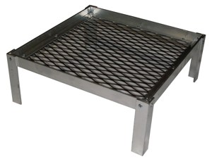
Floor rack: Keeps contents off the floor of the dewar. Dimensions: 9 3/4" square, mesh sits 3" off the floor. Dry ice is placed under the rack for ballast.
Thermocouples (TCs): Place one thermocouple (TCs) under the tissue on the rack. Anchor with wire twist ties at multiple locations. Attach the main TC to the lead wire of the first TC so that it's in the air rather than touching anything. Use multiple attachments. A third TC may be tucked inside the tissue as an indicator of deeper cooling. Anchor it as well. As the lid is placed, make sure all the wires are opposite the fan and do not have slack that could become tangled in the fan.
Use the Subzero Cooldown Software for control and logging.